Monday, April 22, 2013

What is Metal Stamping?


Metal stamping is a system of processes focusing on sheet metal manufacturing. This is one big chunk of the whole science & art of metalworking.

How do they do it?
In the task of building structures, large or small scale, metal stamping is responsible for the processes of punching, blanking, piercing, embossing, drawing, bending, forming, flanging, and coining the metals as needed. Now that’s too much responsibility that requires precision!
Such stages of stamping are carried out until the desired shape and form of the material is achieved. What happens is that sheets of metal are being cut, formed, and shaped by feeding and pressing them between high tonnage stamping dies. This is done in mass production so that parts developed through the process are generally low cost.

What is it for?
This science of metalworking has long been utilized over the millennia, and its cost-effective and mass-producing nature makes it an irreplaceable process for a number of industries. Industries range from intricate production such as jewelry, surgical instruments, and auto parts, to massive manufacturing such as ships, engineering machines, and bridges.
A vital part of the car manufacturing process, metal stamping requires much precision. Avail of metal stamping services only at reputable companies such as Roberts AIPMC.

Progressive stamping
One operation of metal stamping is called progressive stamping which applies at least three of the many stamping operations with one machine. An example of this is one that involves punching, coining, and bending. Using a progressive stamping die and a reciprocating machine press, a strip of metal is fed inside the die as the press moves up. Then the metal is stamped the moment the press moves down and closes the die. This is done in alternating pattern, producing one part after another in seconds.

 What to look for in a metal stamping company
 Like all other processes, quality assurance is being employed before and after metal stamping. General requirements for pre-processing include operator safety and machine press precision, while post-processing requirements include product dimensions, hardness, and other quality conformances. Among many considerations to make in choosing which metal stamping machine to use or company to avail the service of, quality assurance should be an utmost priority.  Other closely related factors to be considered are the value for money and additional relevant services.


Quality assurance should be a top priority when choosing a company for your metal stamping needs.
Stamping simulation to ensure quality

Speaking of quality, a technology called stamping simulation has been developed to ensure just that. We do not want to incur defects such as wrinkles, dents, splits, and material thinning on our products so this simulation calculates the whole process before operation in order to predict potential problems. This way, the machine specialist is able to manage and prevent the fluke before it even happens. This simulation process not only prompts product defects but also predicts lead time (the time it takes to finish the service from order to delivery) and production cost, as these to elements are greatly affected by the incurrence of defects. As such, if proper simulation prevents the stamping process from acquiring supposedly avoidable defects, the whole process could be faster and cheaper. After all, that is what metal stamping is all about- metalworking for quality and productivity.

Metal Stamping Quality Control


Metal stamping is a form of metalworking that is completed using various levels of difficulty. Almost anyone can form their own jewelry, flowers, numbers and letters out of metal using metal stamping kits or other tools. The higher the quality of the metal used, the longer these personal things will last. Metal stamping is also an industrial fabrication process used to create weaponry, vehicle components, dollar bill changers, vending machines, decorative sheet metal parts, medical life-saving devices, and many other items.

Stamping includes a variety of sheet-metal forming manufacturing processes, such as punching using a machine press or stamping press, blanking, embossing, bending, flanging, and coining. This could be a single stage operation where every stroke of the press produce the desired form on the sheet metal part, or could occur through a series of stages. The process is usually carried out on sheet metal, but can also be used on other materials, such as polystyrene.

When working with metal stamping in the industrial world, material quality is very important. A metal stamping company may work with aerospace or medical industries creating products that can save lives-if the metal used is of low quality, lives can be destroyed instead.

Stamping simulation is a technology that calculates the process of sheet metal stamping, predicting common defects such as splits, wrinkles, springback and material thinning. Also known as forming simulation, the technology is a specific application of non-linear finite element analysis. The technology has many benefits in the manufacturing industry, especially the automotive industry, where lead time to market, cost and lean manufacturing are critical to the success of a company.

Recent research by the Aberdeen research company (October 2006) found that the most effective manufacturers spend more time simulating upfront and reap the rewards towards the end of their projects.

Stamping simulation is used when a sheet metal part designer or toolmaker desires to assess the likelihood of successfully manufacturing a sheet metal part, without the expense of making a physical tool. Stamping simulation allows any sheet metal part forming process to be simulated in the virtual environment of a PC for a fraction of the expense of a physical tryout.

Results from a stamping simulation allow sheet metal part designers to assess alternative designs very quickly to optimize their part for low cost manufacture.

Quality control is important, from verifying the metal when it's received to complete testing and inspection once the product is completed. Metal stamped parts can be made into fuel injectors for an automobile, engines in an aircraft, bayonet assemblies, and navigation systems used by the military. With components that can take lives if they fail, it's important to ensure the company you're working with takesquality control very seriously.

First inspection of the material when it is received is an important quality control process. If the metal company can verify where the materials that will be used in production come from, it is likely they take care to make sure your components do not fail on you. Material identification provides documentation as to where the metal has been before being used in fabrication; it shows where it's made and how it's transferred. By using metals from reputable sources, metal stampings are more durable, smoother, and last longer than questionable materials.

Final inspection of the completed component is just as important as material identification. By performing non-destructive testing and other inspection methods on the product, any defaults or other issues will be noticed. A company with high quality standards keeps their rejected products to less than 1%. This shows thatquality control is completed during every step of the fabrication process.

Metal stamping prototypes are a great way to ensure that the final fabrication of all parts will be correct in tolerance, size, durability, and design. Whether the prototype is a working part or not, working with companies who offer this as an option can mean the difference between getting exactly what you want and a completed order that doesn't match your needs.

Wednesday, April 3, 2013

Die casting

Die casting is a metal casting process that is characterized by forcing molten metal under high pressure into a mould cavity. The mold cavity is created using two hardened tool steel dies which have been machined into shape and work similarly to an injection mold during the process. Most die castings are made from non-ferrous metals, specifically zinc, copper, aluminium, magnesium, lead, pewter and tin based alloys. Depending on the type of metal being cast, a hot- or cold-chamber machine is used.

The casting equipment and the metal dies represent large capital costs and this tends to limit the process to high volume production. Manufacture of parts using die casting is relatively simple, involving only four main steps, which keeps the incremental cost per item low. It is especially suited for a large quantity of small to medium sized castings, which is why die casting produces more castings than any other casting process. Die castings are characterized by a very good surface finish (by casting standards) and dimensional consistency.
Two variants are pore-free die casting, which is used to eliminate gas porosity defects; and direct injection die casting, which is used with zinc castings to reduce scrap and increase yield.


Die casting equipment was invented in 1838 for the purpose of producing movable type for the printing industry. The first die casting-related patent was granted in 1849 for a small hand operated machine for the purpose of mechanized printing type production. In 1885, Otto Mergenthaler invented the linotype machine, an automated type casting device which became the prominent type of equipment in the publishing industry. Other applications grew rapidly, with die casting facilitating the growth of consumer goods and appliances by making affordable the production of intricate parts in high volumes.

In 1966, General Motors released the acurad process.


Cast metals
  • Zinc: the easiest metal to cast; high ductility; high impact strength; easily plated; economical for small parts; promotes long die life.
  • Aluminium: lightweight; high dimensional stability for complex shapes and thin walls; good corrosion resistance; good mechanical properties; high thermal and electrical conductivity; retains strength at high temperatures.
  • Magnesium: the easiest metal to machine; excellent strength-to-weight ratio; lightest alloy commonly die cast.
  • Copper: high hardness; high corrosion resistance; highest mechanical properties of alloys die cast; excellent wear resistance; excellent dimensional stability; strength approaching that of steel parts.
  • Lead and tin: high density; extremely close dimensional accuracy; used for special forms of corrosion resistance. Such alloys are not used in foodservice applications for public health reasons. Type metal, an alloy of Lead, Tin and Antimony (with sometimes traces of Copper) is used for casting hand set type in letterpress printing and hot foil blocking. Traditionally cast in hand jerk moulds now predominantly die cast after the industrialisation of the type foundries. Around 1900 the slug casting machines came onto the market and added further automation with sometimes dozens of casting machines at one newspaper office.
Metal Minimum section Minimum draft
Aluminium alloys 0.89 mm (0.035 in) 1:100 (0.6°)
Brass and bronze 1.27 mm (0.050 in) 1:80 (0.7°)
Magnesium alloys 1.27 mm (0.050 in) 1:100 (0.6°)
Zinc alloys 0.63 mm (0.025 in) 1:200 (0.3°)
 Equipment
Hot-chamber machines
Cold-chamber machines
Dies
Die and component material and hardness for various cast metals
Die component Cast metal
Tin, lead & zinc Aluminium & magnesium Copper & brass
Material Hardness Material Hardness Material Hardness
Cavity inserts P20 290–330 HB H13 42–48 HRC DIN 1.2367 38–44 HRC
H11 46–50 HRC H11 42–48 HRC H20, H21, H22 44–48 HRC
H13 46–50 HRC
Cores H13 46–52 HRC H13 44–48 HRC DIN 1.2367 40–46 HRC
DIN 1.2367 42–48 HRC
Core pins H13 48–52 HRC DIN 1.2367 prehard 37–40 HRC DIN 1.2367 prehard 37–40 HRC
Sprue parts H13 48–52 HRC H13
DIN 1.2367
46–48 HRC
44–46 HRC
DIN 1.2367 42–46 HRC
Nozzle 420 40–44 HRC H13 42–48 HRC DIN 1.2367
H13
40–44 HRC
42–48 HRC
Ejector pins H13 46–50 HRC H13 46–50 HRC H13 46–50 HRC
Plunger shot sleeve H13 46–50 HRC H13
DIN 1.2367
42–48 HRC
42–48 HRC
DIN 1.2367
H13
42–46 HRC
42–46 HRC
Holder block 4140 prehard ~300 HB 4140 prehard ~300 HB 4140 prehard ~300 HB
Typical die temperatures and life for various cast materials
Zinc Aluminium Magnesium Brass (leaded yellow)
Maximum die life [number of cycles] 1,000,000 100,000 100,000 10,000
Die temperature [C° (F°)] 218 (425) 288 (550) 260 (500) 500 (950)
Casting temperature [C° (F°)] 400 (760) 660 (1220) 760 (1400) 1090 (2000)
Process
Inspection
Lubricants
Advantages and disadvantages
  • Excellent dimensional accuracy (dependent on casting material, but typically 0.1 mm for the first 2.5 cm (0.005 inch for the first inch) and 0.02 mm for each additional centimeter (0.002 inch for each additional inch).
  • Smooth cast surfaces (Ra 1–2.5 micrometres or 0.04–0.10 thou rms).
  • Thinner walls can be cast as compared to sand and permanent mold casting (approximately 0.75 mm or 0.030 in).
  • Inserts can be cast-in (such as threaded inserts, heating elements, and high strength bearing surfaces).
  • Reduces or eliminates secondary machining operations.
  • Rapid production rates.
  • Casting tensile strength as high as 415 megapascals (60 ksi).
  • Casting of low fluidity metals.


The main die casting alloys are: zinc, aluminium, magnesium, copper, lead, and tin; although uncommon, ferrous die casting is also possible. Specific die casting alloys include: ZAMAK; zinc aluminium; aluminium to, e.g. The Aluminum Association (AA) standards: AA 380, AA 384, AA 386, AA 390; and AZ91D magnesium. The following is a summary of the advantages of each alloy:
Maximum weight limits for aluminium, brass, magnesium, and zinc castings are approximately 70 pounds (32 kg), 10 lb (4.5 kg), 44 lb (20 kg), and 75 lb (34 kg), respectively.

The material used defines the minimum section thickness and minimum draft required for a casting as outlined in the table below. The thickest section should be less than 13 mm (0.5 in), but can be greater.
There are two basic types of die casting machines: hot-chamber machines and cold-chamber machines. These are rated by how much clamping force they can apply. Typical ratings are between 400 and 4,000 st (2,500 and 25,000 kg).


Schematic of a hot-chamber m

achine


Hot-chamber machines, also known as gooseneck machines, rely upon a pool of molten metal to feed the die. At the beginning of the cycle the piston of the machine is retracted, which allows the molten metal to fill the "gooseneck". The pneumatic or hydraulic powered piston then forces this metal out of the gooseneck into the die. The advantages of this system include fast cycle times (approximately 15 cycles a minute) and the convenience of melting the metal in the casting machine. The disadvantages of this system are that high-melting point metals cannot be utilized and aluminium cannot be used because it picks up some of the iron while in the molten pool. Due to this, hot-chamber machines are primarily used with zinc, tin, and lead based alloys.


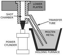
A schematic of a cold-chamber die casting machine.

These are used when the casting alloy cannot be used in hot-chamber machines; these include aluminium, zinc alloys with a large composition of aluminium, magnesium and copper. The process for these machines start with melting the metal in a separate furnace. Then a precise amount of molten metal is transported to the cold-chamber machine where it is fed into an unheated shot chamber (or injection cylinder). This shot is then driven into the die by a hydraulic or mechanical piston. This biggest disadvantage of this system is the slower cycle time due to the need to transfer the molten metal from the furnace to the cold-chamber machine.


The ejector die half


The cover die half
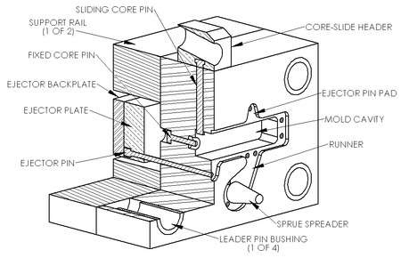
Two dies are used in die casting; one is called the "cover die half" and the other the "ejector die half". Where they meet is called the parting line. The cover die contains the sprue (for hot-chamber machines) or shot hole (for cold-chamber machines), which allows the molten metal to flow into the dies; this feature matches up with the injector nozzle on the hot-chamber machines or the shot chamber in the cold-chamber machines. The ejector die contains the ejector pins and usually the runner, which is the path from the sprue or shot hole to the mold cavity. The cover die is secured to the stationary, or front, platen of the casting machine, while the ejector die is attached to the movable platen. The mold cavity is cut into two cavity inserts, which are separate pieces that can be replaced relatively easily and bolt into the die halves.

The dies are designed so that the finished casting will slide off the cover half of the die and stay in the ejector half as the dies are opened. This assures that the casting will be ejected every cycle because the ejector half contains the ejector pins to push the casting out of that die half. The ejector pins are driven by an ejector pin plate, which accurately drives all of the pins at the same time and with the same force, so that the casting is not damaged. The ejector pin plate also retracts the pins after ejecting the casting to prepare for the next shot. There must be enough ejector pins to keep the overall force on each pin low, because the casting is still hot and can be damaged by excessive force. The pins still leave a mark, so they must be located in places where these marks will not hamper the castings purpose.
Other die components include cores and slides. Cores are components that usually produce holes or opening, but they can be used to create other details as well. There are three types of cores: fixed, movable, and loose. Fixed cores are ones that are oriented parallel to the pull direction of the dies (i.e. the direction the dies open), therefore they are fixed, or permanently attached to the die. Movable cores are ones that are oriented in any other way than parallel to the pull direction. These cores must be removed from the die cavity after the shot solidifies, but before the dies open, using a separate mechanism. Slides are similar to movable cores, except they are used to form undercut surfaces. The use of movable cores and slides greatly increases the cost of the dies. Loose cores, also called pick-outs, are used to cast intricate features, such as threaded holes. These loose cores are inserted into the die by hand before each cycle and then ejected with the part at the end of the cycle. The core then must be removed by hand. Loose cores are the most expensive type of core, because of the extra labor and increased cycle time. Other features in the dies include water-cooling passages and vents along the parting lines. These vents are usually wide and thin (approximately 0.13 mm or 0.005 in) so that when the molten metal starts filling them the metal quickly solidifies and minimizes scrap. No risers are used because the high pressure ensures a continuous feed of metal from the gate.

The most important material properties for the dies are thermal shock resistance and softening at elevated temperature; other important properties include hardenability, machinability, heat checking resistance, weldability, availability (especially for larger dies), and cost. The longevity of a die is directly dependent on the temperature of the molten metal and the cycle time. The dies used in die casting are usually made out of hardened tool steels, because cast iron cannot withstand the high pressures involved, therefore the dies are very expensive, resulting in high start-up costs. Metals that are cast at higher temperatures require dies made from higher alloy steels.
The main failure mode for die casting dies is wear or erosion. Other failure modes are heat checking and thermal fatigue. Heat checking is when surface cracks occur on the die due to a large temperature change on every cycle. Thermal fatigue is when surface cracks occur on the die due to a large number of cycles.

The following are the four steps in traditional die casting, also known as high-pressure die casting these are also the basis for any of the die casting variations: die preparation, filling, ejection, and shakeout. The dies are prepared by spraying the mold cavity with lubricant. The lubricant both helps control the temperature of the die and it also assists in the removal of the casting. The dies are then closed and molten metal is injected into the dies under high pressure; between 10 and 175 megapascals (1,500 and 25,400 psi). Once the mold cavity is filled, the pressure is maintained until the casting solidifies. The dies are then opened and the shot (shots are different from castings because there can be multiple cavities in a die, yielding multiple castings per shot) is ejected by the ejector pins. Finally, the shakeout involves separating the scrap, which includes the gate, runners, sprues and flash, from the shot. This is often done using a special trim die in a power press or hydraulic press. Other methods of shaking out include sawing and grinding. A less labor-intensive method is to tumble shots if gates are thin and easily broken; separation of gates from finished parts must follow. This scrap is recycled by remelting it.The yield is approximately 67%.
The high-pressure injection leads to a quick fill of the die, which is required so the entire cavity fills before any part of the casting solidifies. In this way, discontinuities are avoided, even if the shape requires difficult-to-fill thin sections. This creates the problem of air entrapment, because when the mold is filled quickly there is little time for the air to escape. This problem is minimized by including vents along the parting lines, however, even in a highly refined process there will still be some porosity in the center of the casting.
Most die casters perform other secondary operations to produce features not readily castable, such as tapping a hole, polishing, plating, buffing, or painting.
After the shakeout of the casting it is inspected for defects. The most common defects are misruns and cold shuts. These defects can be caused by cold dies, low metal temperature, dirty metal, lack of venting, or too much lubricant. Other possible defects are gas porosity, shrinkage porosity, hot tears, and flow marks. Flow marks are marks left on the surface of the casting due to poor gating, sharp corners, or excessive lubricant.
Water-based lubricants, called emulsions, are the most commonly used type of lubricant, because of health, environmental, and safety reasons. Unlike solvent-based lubricants, if water is properly treated to remove all minerals from it, it will not leave any by-product in the dies. If the water is not properly treated, then the minerals can cause surface defects and discontinuities. There are four types of water-based lubricants: oil in water, water in oil, semi-synthetic, and synthetic. Oil in water is the best, because when the lubricant is applied the water cools the die surface by evaporating while depositing the oil, which helps release the shot. A common mixture for this type of lubricants is thirty parts water to one part oil, however in extreme cases a ratio of 100:1 is used.

Oils that are used include heavy residual oil (HRO), animal fats, vegetable fats, and synthetic fats. HROs are gelatinous at room temperature, but at the high temperatures found in die casting, they form a thin film. Other substances are added to control the emulsions viscosity and thermal properties; these include graphite, aluminium, and mica. Other chemical additives are used to inhibit rusting and oxidation. Emulsifiers are added to water-based lubricants, so that oil based additives can be mixed into the water; these include soap, alcohol esters, and ethylene oxides.
Historically, solvent-based lubricants, such as diesel fuel and kerosene, were commonly used. These were good at releasing the part from the dies, but a small explosion occurred during each shot, which led to a build-up of carbon on the mold cavity walls. However, they were easier to apply evenly than water-based lubricants.
Advantages:


The main disadvantage to die casting is the very high capital cost. Both the casting equipment required and the dies and related components are very costly, as compared to most other casting processes. Therefore to make die casting an economic process a large production volume is needed. Other disadvantages include: the process is limited to high-fluidity metals and casting weights must be between 30 grams (1 oz) and 10 kg (20 lb). In the standard die casting process the final casting will have a small amount of porosity. This prevents any heat treating or welding, because the heat causes the gas in the pores to expand, which causes micro-cracks inside the part and exfoliation of the surface.


Variants
Acurad

Acurad was a die casting process developed by General Motors in the late 1950s and 1960s. The name is an acronym for accurate, reliable, and dense. It was developed to combine a stable fill and directional solidification with the fast cycle times of the traditional die casting process. The process pioneered four breakthrough technologies for die casting: thermal analysis, flow and fill modeling, heat treatable and high integrity die castings, and indirect squeeze casting.

The thermal analysis was the first done for any casting process. This was done by creating an electrical analog of the thermal system. A cross-section of the dies were drawn on Teledeltos paper and then thermal loads and cooling patterns were drawn onto the paper. Water lines were represented by magnets of various sizes. The thermal conductivity was represented by the reciprocal of the resistivity of the paper.

The Acurad system employed a bottom fill system that required a stable flow-front. Logical thought processes and trial and error were used because computerized analysis did not exist yet; however this modeling was the precursor to computerized flow and fill modeling.

The Acurad system was the first die casting process that could successfully cast low-iron aluminum alloys, such as A356 and A357. In a traditional die casting process these alloys would solder to the die. Similarly, Acurad castings could be heat treated and meet the U.S. military specification MIL-A-21180.

Finally, the Acurad system employed a patented double shot piston design. The idea was to use a second piston (located within the primary piston) to apply pressure after the shot had partially solidified around the perimeter of the casting cavity and shot sleeve. While the system was not very effective, it did lead the manufacturer of the Acurad machines, Ube Industries, to discover that it was just as effective to apply sufficient pressure at the right time later in the cycle with the primary piston; this is indirect squeeze casting.

Pore-free

When no porosity is allowed in a cast part then the pore-free casting process is used. It is identical to the standard process except oxygen is injected into the die before each shot to purge any air from the mold cavity. This causes small dispersed oxides to form when the molten metal fills the die, which virtually eliminates gas porosity. An added advantage to this is greater strength. Unlike standard die castings, these castings can be heat treated and welded. This process can be performed on aluminium, zinc, and lead alloys.

Heated-manifold direct-injection

Heated-manifold direct-injection die casting, also known as direct-injection die casting or runnerless die casting, is a zinc die casting process where molten zinc is forced through a heated manifold and then through heated mini-nozzles, which lead into the molding cavity. This process has the advantages of lower cost per part, through the reduction of scrap (by the elimination of sprues, gates and runners) and energy conservation, and better surface quality through slower cooling cycles.

Semi-solid

Semi-solid die casting uses metal that is heated between its liquidus and solidus, so that it is "slushy". This allows for more complex parts and thinner walls.


Metal-Stamping Overview


The metal-stamping process is described in general, focusing on types of stamping presses and tooling, as well as other equipment that comprises a complete stamping-press line. The use of forming lubricants and the process of part design is also discussed.
A stamping operation requires talented people and the right equipment to perform successfully. How does the stamping process work, and how are equipment and personnel employed to make sure quality parts are stamped consistently?
A stamped sheetmetal part requires able creators backed by talented personnel who allow their machinery—from stamping presses to tooling--to reach its technological potential.

Designing a part 

The birth of a stamped metal part is the designer’s drawing board, perhaps the result of a request from a specifier. The designer must plan a particular part while considering a multitude of factors. How is the part expected to interact with other parts and best fit into a component or assembly? Must the part be light in weight? What forces must it withstand? How long must it last? What size should it be? What is the environment, and how will material selection influence how the part performs in that environment? What technology and machinery is available in order to construct this part in an efficient and cost-effective manner? Will the part be coated or must it be cleaned? If so, how does that affect the choice of material and types of lubrication required for manufacture?

Quality people and equipment required 

Questions asked and answered, the proposed part enters the realm of manufacturing. The effective metal-stamping operation, especially an operation serving multiple clients with multiple requirements, boasts an array of flexible equipment engineered and maintained to efficiently produce a variety of parts. The employees overseeing and operating shop-floor machinery must be well-trained to take advantage of the technology.

Stamping presses serve specific needs 

Obviously, stamping presses are the heart of any sheetmetal-stamping operation. Presses come in varying tonnages, configurations and means of operation. The majority of stamping presses can be classified as mechanical or hydraulic. Mechanically driven presses typically boast higher operating speeds—surpassing 2000 strokes/min. to produce parts rapidly. Relatively simple 2D parts are ideally created in mechanical presses, parts such as razor blades or electrical contacts. Hydraulically powered presses traditionally offered force control throughout the entire forming stroke, unlike traditional mechanical presses that ramp up force as the press ram descends on the work material. Though typically slower than mechanical presses, hydraulic presses, with this total force control, have been the machinery of choice to produce deeper 3D parts with cup or sink recesses. Producing parts with depth in a stamping press is referred to as drawing.
In recent years, these formerly cut-and-dried distinctions between mechanical and hydraulic presses have blurred as new press and press-control technologies enable each to assume characteristics of the other. A newer development, servo-powered presses, which are technically mechanical presses often referred to as servo presses, utilize servo drives to bring benefits of hydraulic and mechanical presses into a single machine.

Increasingly complex tooling 

Of course, a stamping press would just be a machine that makes noise were it not for the tooling inside. One-hit dies represent the simplest form of tooling, where one press hit pounds out a complete part, or at least a shape that travels to secondary machinery for completion or to another one-hit die in another press. Progressive dies, containing multiple stations, add features to a part with each press hit as the base material travels along the die in a strip, knopwn as a carrier strip. In this manner a part is progressively formed. Transfer dies can be considered a combination of one-hit and progressive dies. Here, a material blank—without a carrier strip--travels from die to die, eventually forming a complete part. Many large drawn parts are produced via transfer dies. Transfer dies require mechanisms to physically lift a part from one die station and deposit it into the next. This is accomplished through the use of a transfer press—essentially a specialized mechanical press—or via a part-transfer system attached to an existing press.

Over the years, owing to new technology and efforts to reduce costly and time-consuming secondary operations that take place away from the press, more and more work occurs in the tooling. The result: more complicated and costly stamping dies. Given this fact, die design, maintenance, protection and utilization are so important to the metal-stamping process that a manufacturer will have on staff personnel dedicated to tooling issues.

The high cost of hard tooling such as stamping dies, and the care required to allow this tooling to produce part after part to rigid specifications, demand attention to detail in this area. To protect tooling, a die designer or metal stamper will incorporate various controls and sensors into the process. Often, sensors will be embedded into tooling to ensure presence, and correct orientation and shape of the part material. Die components such as punches may be built with and/or coated with special material. These tool coatings allow for creation of higher-quality stampings while increasing tool life. Many stamping operations, especially those tasked with performing multiple jobs on a single press line, incorporate quick-die-change (QDC) equipment. Such equipment—rolling bolsters, die carts, clamps, etc.—allow rapid changeout of tooling from one job run to the next in order to keep presses running.

Forming lubricants are key to part quality and equipment life 

Proper lubrication within the tooling is essential to the protection of dies and presses, and also to the production of quality parts. Depending on the part material, type of part to be produced and type of tooling employed, specific forming fluids are used. Various lubricant formulations exhibit properties that best serve specific stamping requirements. In some cases, material is coated with lubricant prior to entering the press. In other cases, forming fluids are applied to the part material and tooling during the stamping process.
Lubricant selection reaches beyond part, tooling and material considerations. More and more, safety and regulatory concerns affect selection. Lubricants may be required to be reclaimed or disposed of safely, and must not pose a hazard to employees or the environment. Stamping-lubricant and lube-system suppliers have, therefore, developed fluid formulations and methods of delivery and reclamation to address these concerns.

Functional stamping-press line has many components 

Stamping a part involves more than a press, tooling and forming fluids. A fully outfitted press line includes feed machinery that delivers part material to the press. This includes equipment to transport stage and deliver coiled material into the press, or other equipment to feed a press individual material blanks. In multiple-press lines, robots or other part-handling machinery transport part material from press to press, then capture finished parts for placement in bins or racks. Conveyors or other material-handling equipment also move parts or collect and transport scrap. 

Metal-Stamping Presses and Stamping Operations


Metal-stamping presses can be classified according to drive mechanism—mechanical, hydraulic, servo--and press-frame construction—gap-frame, c-frame, straightside. These classifications, detailed here, impart certain important characteristics to the press. Also described are stamping processes—blanking, piercing, notching, bending, drawing, coining.  

Presses function as the signature pieces of shopfloor equipment in a stamping operation. The types of metal-stamping presses depend on the nature of the stamping work. Stamping presses function by providing energy to force a ram downward, providing force for the stamping dies and tooling. Attached to the press ram is an upper die. The ram descends toward the lower die. Located between these die halves is the part material. As the die halves meet, a part is cut, shaped or otherwise worked within the tooling. The ram then ascends, a part is removed or the part material is indexed, and the stamping cycle repeats. Sounds simple. But generating the force necessary to stamp metal parts, especially given newer, higher-strength steels, demands attention to press design and method of press motion. Designs and drive mechanisms impart characteristics to stamping-press operations that affect the ability to form parts. With stampers demanding flexibility in these expensive pieces of capital equipment, press manufactures have responded, and press technology has evolved to serve stampers’ diverse needs.

Stamping presses generally conform to two basic designs. Gap-frame presses, also referred to as c-frame presses because of their shape, are connected from bottom to top at one location, behind the work area. These presses feature lower capacities and typically perform as stand-alone machines, often manually fed. Straightside presses are supported on each side of their rectangular footprint, and given their robust construction they are less susceptible to deflection arising from off-center loading (a condition where stresses drive the ram out of its normal, parallel condition) than gap-frame presses. Due to their beefed-up framework, straightside presses offer high capacities and often operate in press lines, either teamed with other straightside presses or outfitted with ancillary equipment. 

Hydraulic presses 
Hydraulic presses depend upon the pressurization of hydraulic fluid in cylinders to provide force to the ram. These presses, by controlling the pressure, allow force control, and full force if need be, throughout the motion of the ram as the part is formed. This amount of vertical motion is referred to as the stroke length. The notion of force control throughout the stroke is important. In certain applications, such as working with difficult-to-form material, or when performing drawing operations, force control throughout the stroke, and the ability to provide full power throughout the stroke, is needed for proper forming. Force control and full-force capability, along with relatively simple maintenance and lower energy costs, are major reasons why stampers may consider choosing a hydraulic press over its mechanical kin.

At one time, hydraulic presses were seen as maintenance-intensive, given the occurrences of leaking seals and hoses attributed to the fluid-handling nature of the machines. In recent years, better hydraulic-system designs and improved seals and connectors have all but eliminated such problems.
Applications for hydraulic presses include deep drawing, high-tonnage blanking at lower speeds, and short job runs, since press speed is less critical given smaller part volumes. Hydraulic presses are available in capacities from 20 to 10,000 tons, with work strokes from 0.4 to 32 in.

Mechanical presses 
Drive methods of mechanical presses differ from those of their hydraulic counterparts. In most mechanical stamping presses, flywheels, driven by motors, store energy that is then transferred to ram motion. Because flywheels expend energy with each downstroke of the ram, they slow down. That energy must be restored, and is, by the motor in time for the next stamping-press cycle to begin. Mechanical presses operate at much faster speeds—well above 1,000 strokes/min.--than hydraulic presses, but work strokes are shorter, due to the fact that full force develops in a mechanical press near the bottom position of the press stroke. With their high-speed capability, mechanical presses get the call for many high-volume metal-stamping jobs where parts are flat or at least somewhat shallow. Mechanical presses fare well in stamping flat or low-depth parts. That is because mechanical presses can only provide full forming force in a smaller stroke range than hydraulic presses. Typical applications for mechanical presses include high-speed blanking, precision flat-part production and shallow drawing.
Mechanical press capacities range from 20 to about 6,500 tons with strokes from 0.2 to 20 in.

Servo presses 
Recent years have brought new  technology in the form of servo-driven presses, or servo presses, to metal stampers. Servo presses, though technically classified as mechanical presses, employ servo drives to provide power, negating the need for flywheels. Advantages of servo presses include the ability to control the stamping press’ stroke length and velocity. Another plus: Servo presses allow for dwell time at the bottom of a press stroke, where forming work occurs. This is ideal when material must be given time to flow or stretch into a part shape. Features such as these bring benefits of mechanical and hydraulic presses into a single machine, providing flexibility to the stamper.

Types of metal-stamping operations 
Given the proper tooling, metal-stamping presses can perform a multitude of part-shaping operations.
  • Blanking: Cutting flat sheetmetal into a defined size and shape. Typically performed in one hit of the press, the result may be a finished part or a blank destined for further forming or processing into its final shape.
  • Piercing: Similar to blanking, the pierced piece instead is scrapped, with the surrounding material as the part.
  • Notching: Similar to piercing, but here material is removed from the edges of the workpiece.
  • Bending: Sometimes referred to as forming, tooling bends workpiece material into various angles.
  • Drawing: The press essentially stretches sheetmetal to a depth.
  • Coining: The die forms an imprint on the workpiece.

Tool & Die Overview


Stamping tooling and stamping dies are detailed here, including, progressive dies, one-hit dies and transfer dies. We will also discuss tool steels and tool coatings in addition to in-die sensors, in-die welding and in-die tapping. Die design is also discussed.


Sheetmetal stamping, incorporating bending, piercing and other processes, depends on a various types of tooling to get the job done. In a metal-stamping operation, the die, or tooling, is where the action is. Located within the stamping-press window, tooling uses the energy created by press movement to produce a sheetmetal part. The tooling can cut sheetmetal and perform many other part-producing functions such as piercing, bending and trimming. With the addition of specialized modules or other equipment, tooling can even perform tapping, welding and inserting (of nuts or other pieces of hardware).

What is a die? 

In simple terms, a die set contains two halves, the die punch and the die cavity, with all of the components needed to cut and form a stamped part resting upon a metallic plate called a die shoe. Two die shoes (usually an upper die shoe and a lower die shoe), with components included, form the die set. The size of a die set depends on the size and type of part to be stamped, and the type of work that must be done to produce that part. Some dies, such as those used to create tiny electronic components, may be as small as a few inches across and few inches high. Other dies, such as those used to produce automotive panels, can stretch to more than 10 ft. long and 6 ft. high. A limiting factor in die size is the size of the window opening on a stamping press. 

What is the material makeup of a die? 

Though most sheetmetal stamping is considered a cold-forming process, stresses and forces encountered during the process generate heat. Combating heat, and also combating wear and tear associated with working various types of part material, demands the use of specialized materials in creating dies and tooling components. These materials, collectively referred to as tool steels, are specified primarily according to the type of part material to be stamped and the number of hits required per part run. The introduction of unique steels, driven by automotive-industry needs for high-strength, lightweight parts, have spurred development and use of unique die materials and tool coatings. These materials and coatings allow tooling to hold up while working on these new, high-strength steels.

How are dies classified? 

With a single hit of the press, stamping dies can form complete parts or certain features of a part.  One-hit dies, representing the simplest form of tooling, produce complete parts with a single press hit, or at least a shape that travels to secondary machinery for completion or to another one-hit die in another press. Progressive dies contain multiple stations—think of a series of one-hit dies connected together. Dies of this type add features to a part with each press hit as the base material travels along the die in a strip. In this manner a part is progressively formed. Transfer dies have characteristics of one-hit and progressive dies. With transfer dies, a material blank travels from die to die, eventually forming a complete part. Unlike with a progressive die, parts in a transfer die do not travel from station to station attached to a carrier strip. Rather, mechanisms located outside of the tooling physically lift a part from one die station and deposit it into the next. This is accomplished through the use of a transfer press—essentially a specialized mechanical press—or via a transfer system attached to an existing stamping press. 

How are dies made? 

Design and construction of dies are time-consuming and costly processes. Development of die-design software that simulates the forming process and allows specialists to design tooling on computers has enabled shortened lead times for die delivery. Using such software—once general design programs such as SolidWorks, but now available in various programs tailored for stamping-die design--also can eliminate problems that at one time only showed themselves during tryout after the stamping die was built. Using such software has reduced costs. Also, in some cases die lead time—the time period between die design and production of quality parts in a stamping press using that particular die—has shrunk from months to days.
Dies typically are machined, with components such as pins, punches and springs fastened to the die base. Die components such as punches are particularly susceptible to wear and breakage. Problems with these types of components can cause press shutdowns while tooling is repaired, slowing production and adding cost to the stamping process. To combat this, tooling suppliers have developed methods to change out components quickly. Also, stamping tooling can undergo special coating processes to enhance tool life and ensure production of precision, quality parts even after hundreds of thousands of press hits. 

High-tech tooling replaces costly secondary processes 

As a capital-intensive process, sheetmetal stamping can be quite costly. To remain competitive, metal stampers must employ process efficiencies. One method to improve efficiency is to perform as many processes as possible within the press. Secondary processes that take place away from the stamping press are costly and time-consuming. But performing more and more work within the press—actually, within the tooling—can result in more complicated, and costly, dies. Given this fact, die design, maintenance, protection and utilization are so important to the stamping process that a manufacturer will have personnel dedicated to tooling issues.

The high cost of stamping dies, and the care required to allow these dies to produce part after part to rigid specifications, demand attention to detail in this area. To protect tooling, a die designer or stamper will incorporate various press controls and sensors into the stamping process. Often, sensors will be embedded into tooling to ensure presence, and correct orientation and shape of the part material. These are referred to as in-die sensors. Many stamping operations, especially those tasked with performing multiple jobs on a single press line, incorporate quick-die-change (QDC) equipment. Such equipment—rolling bolsters, die carts, clamps, etc.—allow rapid changeout of tooling from one job run to the next in order to keep presses running.

The right forming fluids can spell stamping success 

Stamping lubricants aid tooling and dies in creating quality parts, while bringing longer tool and die life. Lubricants are available in many formulations depending on factors such as the material to be stamped and the stamping process to be employed. Lubricant-delivery systems ensure that forming fluids reach into critical areas of the tooling and material, without hampering the performance of sensitive components such as in-die sensors.