Wednesday, March 27, 2013

The Tool and Die Making Machines

The tool and die making industry is among the most profitable industries there is. Tool and die making is a process that requires a lot of knowledge and know-how. People who decide to enter this field would need to spend several years studying everything about it and learning its different applications. In short, it is no joke to venture a career in this field.
People who are in this kind of profession are regarded highly by their fellow skilled workers. Their job is to make tools, die them, and make sure that all the objects and products created are in its best possible condition. They also manufacture clothes, pieces of furniture and equipment and car or aircraft parts. They may be found in large industrial and manufacturing plants or in average-sized machine shops.
In order for a tool and die maker to be efficient, he or she should be educated with even the littlest details about how to manufacture stamping dies, jigs, fixtures and plastic molds. Different types of materials would require varying techniques. For example, in stamping dies, force is required from the maker. However, in plastic molding, no force is needed.
As the years went on, the machineries and tools used in tool and die making have developed greatly. One notable person who played a great role in this process is Eli Whitney, an American manufacturer and inventor. His notion of interchangeable parts in planned manufacturing was revolutionary. Because of his studies, he was able to successfully mass-produce firearms and weapons for a war that occurred in 1812.
Since then, tool and die making machines have evolved greatly. The power press came out, then there's the press die, and more. Alongside this, injection molding and die casting took a leap, resulting to more demands for more advanced tools.
Tools and dies are often designed by tool designers and engineers, but a well-experienced and extremely skilled tool and die maker could also do the job. They would be asked to visit a customer's place to check out the whole operation. This would enable them to know if there's something in there that needs improvement.
Back then, they would use blueprints to plan out the necessary steps to proceed with the operation. Everything would then be done manually. Fortunately, today, CAD or computer-aided design and more modern tools and machineries are already available, making things much simpler and faster to accomplish.

The Important Function of Metal Stamping Dies

Metal stamping dies are the devices used in metal stamping machines. Each metal stamping machine can have one or more than one dies depending on the kind of machine. Dies are the main components in metal stamping machines that do the actual casting, punching, cutting and shaping of the metal sheet.
The basic die operations are drawing, shearing and bending. In metal stamping, the metal sheets are placed in a die or a press tool which has a specially designed cavity that gives the preferred shape to the metal sheet. The upper part of the die connects to the press slide while the lower component connects to the press bed. A specific component known as the punch pushes the metal sheet through the die, thus performing the actual shaping operation. The patterns on the dies can be used to emboss or give three-dimensional lettering on the final product.
Dies are placed in sheet metal panels either alone or as a series of presses in a press line. Metal stamping dies and presses can have different input variables on the bases of tonnage, press parallelism, shut height, nitrogen pressure in dies, counterbalance pressure and press speed. These variables can influence the quality of the stamping panel, particularly during die setup. The same stamping press can be reused by replacing one set of dies with another.
The placement of dies in a press is known as die setup. Die setup decides the shut height and binder force. The number of components produced in a die setup is known as a batch.
There are many different kinds of dies such as single station dies, multiple station dies, compound dies, progressive dies and tandem press lines. Most dies are designed by the metal stamping companies who use advanced technologies like CAD to design them according to customer specifications. Another classification of dies is draw dies, trim dies and cam-pierce dies.

Stamping Tools and Die Hot Stamping

Stamping tools are hard tools made with hard materials like steel. Usually hot stamping die is used for stamping metal surfaces. Die is the tooling used to produce a stamped part. A die set assembly has male and female components that actually produce the shaped stamping. Stamping die stamps the design on the metallic surface by using moulding process.
Stamping can be fun when done right. But, you have to have the right stamping tool for precision metal stamping. Latest stamping methods are affordable and provide creative stamping solutions. Stamping tools can be used for stamping metal, foils, wood, leather and plastic. Stamping tools companies usually provide.
    Stamping tools and dies servicesIn-house die designClean & organized tools roomFast tooling modificationsTry-out, first-run and capability Studies

Metal Stamping:
Metal stamping tools and stamping dies are used to produce high volume sheet metal parts using press. Parts can be stamped from any ductile metal to create and achieve almost any desired configuration.
Metal stamping is generally performed on materials .020" to .080" thick with tolerances to ±.001. The process also can be applied to foils as thin as .001". Stamping is also done by machine press. The metal is placed between the press plates and pressed against each other. This deforms the metal into the desired shape.
Die Hot Stamping:
The Die Hot Stamping process is described as relief printing and as the name implies uses printing plates with raised images. Hot stamping is used in graphic arts, plastics and packaging industries. Die hot stamping is versatile. It can print onto all wettable materials - paper and board, thermoplastics and duroplastics, leather, textiles, wood and many other materials.


Thursday, March 7, 2013

Coining Sheet Metal


Coining fabrication is a basic type of bending in which the workpiece is stamped between the punch and die. Both the punch tip and the punch actually penetrate into the metal past the  neutral  axis under a high amount of pressure. The term Coining comes from the idea that when it comes to money each metal coin is made exactly the same as the last despite being mass produced.  From this idea the name Coining was applied to the bending method which creates accurate bends consistently.
Coin Bending Sheet Metal
There are a few significant advantages to coin bending sheet metal, the first of which are high repeatability, precision, and the  ability  to reduce the inside radius to as small as desired.  During the Coining process the material is put under enough pressure that the punch tip penetrates the material at the bottom of the bend and it begins to flow into the die. Because the sheet metal flows during the process of Coining the bend radius formed by Coining is always equal to that of the punch tip. The penetration into the metal also relieves the internal stress and is thought to be a contributing factor to the elimination of  Spring Back.

A final advantage of Coining is that this method does not require sophisticated CNC machines to execute. It does however very large tonnages compared to the other two bending methods, typically it will require 5-8 times the tonnage of Bottom Bending. Because of these tonnage  requirements, wear and tear on the machines will be much greater than air or Bottom Bending. Tooling required for Coining must be robust and this can limit your tooling and geometry options.  Because of the tooling restrictions and the large tonnages required to coin this process is rare in the press brake world.

When determining the V-width for  tooling  it is preferable to use a v-opening of 5*Mt. This reduces the initial inside radius, before the punch tip begins to penetrate, and reduces the amount of metal the tip actually has to penetrate.  The smaller v-opening also means that the surface area between the sheet metal and the bottom die is reduced, this increases the  average  tonnage per area on the inside of the v-opening, the keY-Factor in eliminating Spring Back.  When selecting the tooling for a Coining operation the punch and die should have the same angle as the desired finished bend. Spring back is not taken into consideration when making this selection.  If you desire a 90 ° bend you should select a 90 ° punch and a 90 ° die.
Pros:
  • Accuracy
  • No Spring Back
  • Repeatability
  • No sophisticated machinery
  • Small inside radii are possible
Cons:
  • High tonnage required
  • Tooling limitations
  • Increased wear on machinery
  • Larger brakes required to produce extra tonnage

Formulas For Coining

The actual formulas for Coining are fairly simple as they are just based off of the  formulas  for Air Bending, modified for the affects of Coining. For the tonnage formula below I’ve given 7.5 as a multiplier, this may be higher or lower depending on the material you’re bending.  The rule of thumb I use for this is the higher the tensile strength of the material the higher the tonnage multiplier.  You should always start low and work your way up until you get the desired results. Use the Air Bend Force Chart to find your initial tonnage. You can also reference the tensile strengths for different materials below.

Tonnage = L * F * (Tensile Strength / 45) *7.5

V Opening = 5 * Mt.

Inside Radius = Punch Tip Radius

Tensile Strengths

MaterialSoft (kg/mm^2)Hard (kg/mm^2)
Lead2.5 - 4-
Tin4 - 5-
Aluminum9.3171
Aluminum Alloy Type 42348
Duralumin2648
Zinc1525
Copper22-2830-40
Brass (70:30)3353
Brass (60:40)3849
Phosphor Bronze / Bronze40-5050-75
Nickel Silver35-4555-70
Cold Rolled Iron32-38-
Steel .1% Carbon3240
Steel .2% Carbon4050
Steel .3% Carbon4560
Steel .4% Carbon5672
Steel .6% Carbon7290
Steel .8% Carbon90110
Steel 1.0% Carbon100130
Silicon Steel5565
Stainless Steel65-70-
Nickel44-5057-63

Brake Press Tooling


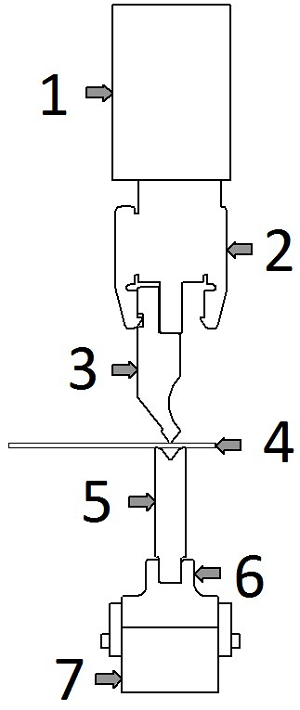
The Basic Structure Of Press Brake Tooling

1 – Upper Beam

The upper beam is an integral part of the press brake and features a kind of rail which the punch holder will mount to.  On down acting brakes this is the part of the machine that moves, transferring power to the work piece.

4 – Punch Holder

The punch holder attaches semi-permanently  to the upper beam and serves to hold a variety of punches.  They come in two basic forms, European and American, understanding the difference is important. See our post on European Vs. American Style Tooling for more information.  Punch holders will typically have a built in shimming mechanism for balancing them with the lower die.

3 – Punch

Punches are the upper part of the tooling system and are classified by their Tip Angle, Relief Shape and their Installed Height. Standard Tip Angles are 30 °, 45 °, 60 °, 75 °, 88 ° and 90 °.  The 30 ° and 45 ° types are known as acute punches. 60 ° and 75 ° Punches are used for Air Bending. 88 ° and 90 ° Punches are used for Bottom Bending. 90 ° Punches will be used for Coining. The relief shape allows for return bends to fold into the punch area.
The installed height of press brake tooling is the distance from the tip of the punch to where it contacts the upper beam / holder. For European Tooling there are 7 standard heights. 65mm, 67mm, 70mm, 90mm, 95mm, 104mm, and 105mm.
Punches come in two styles when connecting to the upper holder, European Style and American Style.  European Tooling has an offset holder (as shown above) where American Tooling has an inline holder. Check our post on  tooling styles for more information.
When bending deep boxes which have long flanges around a base tab you’ll want to investigate different tooling options.  Some are basic such as  extending  the  punch  holder and some are a bit mroe creative such as window bending and 30-60 bending. For more  information  look into this post on  Box Bending.

4 – Work Piece

Commonly referred to as the work piece the sheet metal being bent is the driving force for all tooling selection. The type of material, its mechanical properties and the intended bends drive all other aspects of the tooling set up.  Sheet metal is classified by it’s material and its gauge.  The gauge is a numerical value assigned to the thickness of the metal.  See our Gauge Chart for a better understanding of gauges and tolerances.

5 – Die

The bottom section of the tooling is known as a die.  Dies are classified by the shape of the groove, the number of grooves and the height of the die.  The most common shape of die is a v die, which, as its name suggests, is a block of tooling steel which has a v shaped groove cut into it.  A v die with a single groove is known as a 1V Die, dies with two grooves are known as 2V Dies and so on. 2V Dies will always feature the same angle on both grooves to prevent accidental damage, however the v opening size will typically be different.  This  allows  an operator to quickly switch from bending a light gauge to bending a heavy gauge without having to retrieve a new die. Second to v dies the most common type is a U Die. U dies feature a rectangular cutout with 45 ° chamfered edges and flat tops.  Because of this geometry U Dies lend themselves to having grooves cut into more than one side of the die. It’s not uncommon to see a 3U Die. There is much more information on  3 sided dies here.

6 – Rail

The rail is a manufactured piece of tooling which is attached to the press brake and holds various dies.  The rail typically features a protrusion or groove which matches with the die set.  This piece of tooling allows you to level and straighten a single piece of tooling and then interchange dies with confidence.

7 – Lower Beam / Die Holder

The lower beam is part of the actual press brake which features a kind of vice clamp for holding the raid or die set.  On up acting brakes the lower beam is moves upward to bend the metal.  When inspecting and maintaining your brake it is crucial to make sure the lower beam is clean and level in relation to the punch holder.

Basic Requirements

First the tooling should be of a size and weight which allows for handling, installation and removal. Unless you have a fully automated system there will be an operator responsible for setting up the Brake Press, taking this into account is important to selecting your tooling. Second to the safety of the operator is the accuracy of the tooling geometry.  Variance in the tooling geometry will directly contribute to under or over bending of the work piece, or in extreme cases the damaging of the tooling.  Due to the high tonnages involved in bending any imperfections on the surface of the punch or die can transfer to the workpiece. Third the tooling should have excellent  strength  and wear resistance.  Typically heat treatment is applied to all Brake Press tooling, greatly improving its hardness, strength and subsequently its resistance to fatigue. Finally your tooling should be  interchangeable  between your machines.  There are two basic types of tooling for Brake Presses, American and European, consider which type of machinery and holders you have before purchasing new tooling.

Tooling Strength

During the bending process the tooling will undergo both compressive forces and bending moments. The  repetitive  nature of bending operations the necessity for high strength and wear resistance demands quality steel properly heat treated.  When heat treating steel there are two methods, hardening and thermal refining. To be referred to as tooling the piece should be treated by one of these methods. Strictly speaking punches and dies made from raw, untreated, metal should not be referred to as tooling because it will not be effective when bending.

Hardened Tooling:

Two common steels used for Brake Press tooling are Chromium Molybdenum Steel, Type 4 (SCM4) and Yasuki Steel.  Chromium Molybdenum Steel is a structural steel used in aircraft parts, weapon components, roll cages and structural car parts in addition to their use in tooling. The steel is used for Brake Press tooling because of its receptiveness to heat treatment. Typically this steel will obtain a HRC of 43 to 48 when treated for tooling.  Yasuki Steel is a product of the Japanese company Hitachi and is made from very high quality iron sand.  It has one of the highest purities in commercial steel and is used in knives in addition to tooling.  Like SCM4 Yasuki Steel is very receptive to hardening by heat treatment. Surface treatments like Wilson Tool’s Nitrix Coating can bring the surface hardness of tooling to HRC 70, further preventing wear of the tool’s geometry.
The manufacturing process of hardened steel tooling is typically a 4 step operation; Forming, Hardening, Correcting and Finishing.  First the tool profile is created from the stock material.  Extra material is left on to be removed later.  The majority of the machining and forming is before the hardening stage because after the tool has been hardened it will be difficult to work with.  The tooling is then hardened. Because of the high heat the hardening process the tool will not finish with the  exact  profile as before hand so additional correcting is done before the tool is finished. The tool’s critical areas such as the punch tip and v-opening are then ground by precision  grinders, typically using diamond or CBN coatings.  On a die with a multiple v-opening the different v’s are often ground together from one wheel.

Thermally Refined Tooling:

Steel used for thermally refined tooling is typical a Carbon Steel, S45C. The refining process  unifies the internal structure of the steel increasing its strength and hardness.  Thermally refined tooling will not be as hard as hardened tooling, typically only reaching HRC 23-28.  Thermally refined tooling is typically used for large or complicated pieces. The larger pieces are more difficult to harden due to oven and grinder size restrictions so thermal refining can be preferable.  Small or complicated pieces lend  themselves  to this method in order to eliminate expensive correcting operations.
The manufacturing process of thermally refined steel varies for the large and small pieces. Large pieces follow similar steps as hardened tooling.  Unrefined metal is Formed, Refined, Corrected and Finished.  For small tooling the already Refined Material is Formed and Finished. Generally speaking the reason for the different processes is because refined stock is not available in large pieces due to a property called the mass effect.  The mass effect means that the inside of a large piece of metal will not experience the same refining as the outside of the same piece of stock.  This is because the inside and outside of the material cool at different speeds, resulting in different properties.  When you  machine  away the  outer  section of a large piece of refined stock you risk exposing the inner section which was not treated in the same manor as the  outside. Its  because  of this that it is  recommended  that large tooling be refined after the initial forming.

Handling  & Installation

One of the most important considerations of tooling geometry is the actual size of the tool. Tools will be routinely moved, mounted, aligned, removed and stored in a typical shop.  To have a tool section which requires multiple operators or machinery to load and unload is not practical and should only be used if absolutely necessary.  One piece tooling is often cheaper then sectionalized tooling, and modern manufacturing methods do provide adequate accuracy.   It used to be the case that limitations in grinder’s vertical accuracy per foot meant that single long pieces of tooling would vary more from one end to the other than that sectionalized tooling with an equal total length.  Today this is not a major factor when purchasing from a respectable source.
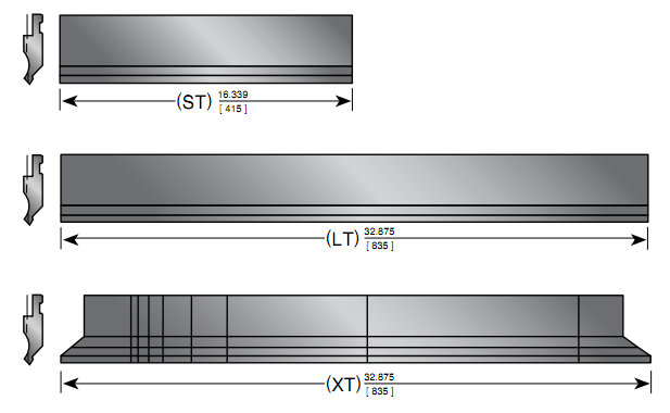
Sectional tooling provides more than just easy  handling, it also allows for more geometry options.
This is a fairly standard break down of sectionalized tooling: 100mm Left and Right Ear, 10mm, 15mm, 20mm, 40mm, 50mm, 200mm and 300mm. In addition most manufacturers offer a 415mm ‘Short’ Section and a 835mm ‘Long’ Section.  By combining different sections a wide variety of possible lengths emerge.
Sheet Metal Hems


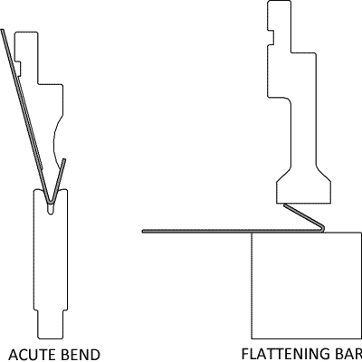
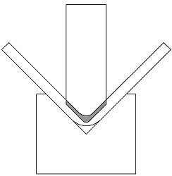
The term hemming has its origins in fabric making where the edge of cloth is folded back on itself and then stitched shut.  In sheet metal hemming means to fold the metal back on itself.  When working with a Brake Press hems are always created in a two step process:
  1. Create a bend with Acute Angle Tooling in the metal, 30° is preferable but 45° will work for some circumstances.
  2. Place the acute bend under a flattening bar and apply enough pressure to finish closing the bend.
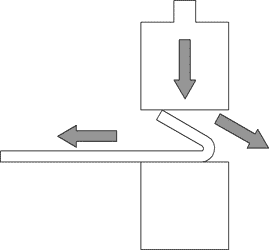
The first step is done the same as any regular acute angle bend.  The second stage of the hemming process requires some additional know how on the part of the Brake Press operator and tool designer because the angle of the sheet metal, the flattening bar wants to slide down and away from the sheet metal.  In addition the work piece wants to slide out from between the bars.  These two forces are known as thrust forces.
Illustration Of The Thrust Forces From Hemming Sheet Metal
This requires that the flattening die be designed to withstand the thrust forces and remain flat.  In addition it requires that the operator put a forward force against the sheet metal to prevent it from sliding out of the die.  These forces are most prominent on thicker work pieces with shorter flanges.  With these factors in mind let’s examine three of the most common forms of hemming set ups and tooling available for press brakes.

Multi Tool Setup, Acute Tooling and Flattening Die

The simplest form of hemming set up is combining two different setups.  The first is an acute setup, where the 30° bend is created using standard tooling.  Once the first bend is made the part is either transferred to another machine, or a new setup is put into the original.  The second setup is a simple flattening bar.  The bend is placed underneath the flattening bar and is closed.  This setup doesn’t require any special tooling and may be preferable for short runs, prototypes or job shops which will need to form a variety of hem lengths.  As individual pieces of Brake Press Tooling the acute tooling and flattening bar are very versatile, and add value outside of hemming.  The draw backs to this system is the obvious requirement of two unique setups, as well there is no thrust control in the flattening process.
Hemming Sheet Metal Without Special Tooling

Two Stage Hemming Punch and Die Combination

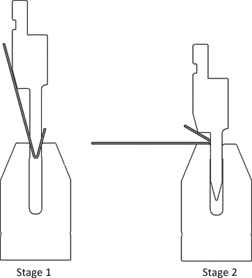
A two stage hemming die works by using a deep channeled die and an acute sword punch.  The first bend uses the channel as a v opening to air form the bend.  In the second stage the punch slides into the channel as the punch is closed and the edge of the punch is used to flatten the sheet metal.  Seating the punch inside the die’s channel redirects the thrust force into the die, which can be more readily secured than the punch itself.  The drawback for this type of die is that it practically requires a CNC control.  Because of the difference in height between the stroke of the first and second stage to adjust manually would be very time consuming.  In addition this type of die can be easily split from over tonnage, reinforcing the need for computer controlled safeties.
Creating A Hem With A Two Stage Die

Three Stage Hemming Punch And Die

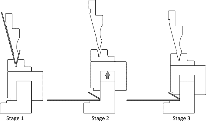
The other most common form of tooling designed specifically for creating hems is a three stage, or accordion type punch and die.  The v opening sits on top of a spring loaded pad, which sits over a bottom pad.  In the first stage the acute bend is created in the v opening after the spring has been compressed and the upper pad is seated on the lower pad.  In the second stage the upper ram is retracted and the springs between the upper and lower pad returns it to its original position.  The sheet metal is then placed between the upper and lower pad and the punch is closed down transferring tonnage through the v die.  Special relief is given to the v die to allow this tool on tool interaction.  The guide between the upper and lower pad prevents the thrust forces from affecting the rest of the tooling.  The lower die also gives the operator something to push the work piece against preventing the sheet metal from sliding out.  This tool is preferred for mechanical, non CNC, brakes because the difference in stroke heights is very small, making adjustment less time consuming.  This set up also allows you to use a standard acute punch.
Hemming Sheet Metal With A Three Stage Die

Tonnage Required For Hemming

The tonnage required for hemming is going to depend on the strength of your material, its thickness and most importantly what type of hem you wish to form.  The tear drop and open hems do not require nearly as much tonnage as a flat hem does.  This is because you are only changing the inside radius minimally, basically you are just continuing the bend past 30°.  When you flatten the metal you are forming a crease and removing the inside radius.  Now you are forming the metal rather than simply bending it.  Below you can see a hemming tonnage chart for cold rolled steel.
Types Of Sheet Metal Hems
Metal ThicknessOpen / Tear Drop Hem TonnageFinished HeightClosed Hem TonnageFinished Height
24 Gauge15.11835.048
22 Gauge20.11850.060
20 Gauge25.13760.072
18 Gauge26.13780.096
16 Gauge38.18195.120
14 Gauge50.216130.150
12 Gauge90.255180.21
10 Gauge100.314210.269
8 Gauge140.445280.329

Uses For Hems

Hems are commonly used to re-enforce, hide imperfections and provide a generally safer edge to handle.  When a design calls for a safe, even edge the added cost of material and processing of a hem is often preferable to other edge treating processes.  Designers should look beyond a single small flat hem to treat edges.  Doubling a hem can create an edge perfectly safe to be handled without almost regard for the initial edge quality.  Adding a hem in the ‘middle’ of a bend profile can open the doors to a variety of profiles not possible without fasteners or welding.  Even without sophisticated seaming machines a combination of two hems can create strong, tight joints with little or minimal fastening.  Hems can even be used to strategically double the thickness of metal in areas of a part which may require extra support.  Hems used in the food service industry should almost always be closed for sanitary purposes (very difficult to clean inside the opening).
Examples Of Uses For Hems
Double Hem Edge – Hem And Double Metal Thickness Bend For Support – Using A Hem To Create Advanced Profiles

Determining Flat Patterns Of Hems

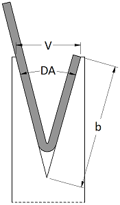
The flat pattern of a hem is not calculated in the same fashion as a typical bend.  This is due to the fact that factors such as the Outside Setback and the K-Factor become useless as the apex of the bend moves to infinity.  Attempting to calculate the allowance for a hem like this will just lead to frustration.  Instead a rule of thumb of 43% material thickness is used when calculating the allowance.  For example if our material is .0598” and we want to achieve a 1/2” hem we will take 43% of .0598, .0257 and add that to the 1/2” giving us 0.5257”.  Thus we must leave 0.5257” on the end of the flat pattern to achieve a 1/2” hem.  It should be noted that this rule of thumb is not 100% accurate.  If you are interested in creating a high accuracy hem you should always bend a sample piece, measure and adjust your layouts.  It’s wise to do this for your commonly hemmed materials and create a chart for future reference.  The minimum size or length of a hem is going to b determined by your v opening of your die.  It is going to be wise to check your hem length after bending because the final step of flattening the metal can be a bit un-predictable in terms of how it stretches and flattens.  Using a standard minimum flange length should get you close enough for most applications.  Remembering the Air Bend Force Chart the minimum flange length for an acute tool is:
b={\dfrac{\dfrac {V}{2}}{\sin{(DA)}}}
The Minimum Flange Length For Bending And Acute Angle

Rotary Die


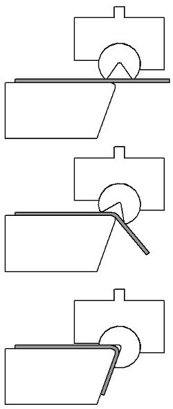
Bending Sheet Metal With A Rotary Die

A rotary die is a special type of punch die combination which bends the sheet metal using a rotating cylinder with a v opening cut into the side of the cylinder.   The cylinder is seated into a saddle making up the punch section of the die.   The sheet metal lays on an anvil and the rotary die is pushed down on top of it.   As the die engages the sheet it begins to rotate and bends the metal around the tip of the anvil. Sometimes a backing plate (not shown) called a heel keeps the saddle steady as the machine is closed and the bend completed.
Rotary dies provide a number of benefits over traditional punch die combination.   The rotary die will clamp the sheet metal before bending providing a secure work piece without any sliding. As the sheet is bent the worker side does not move providing a safer and more ergonomic experience for the operator.   The fact that the sheet does not move also means the the operator does not have to ‘chase’ the metal while it’s being bent, improving the quality of the bend. Rotary dies can also bend beyond 90 ° like traditional tooling to compensate for Spring Back.   Many operations can have their required tonnage reduced by using a rotor die.   Rotary dies also allow for the creation of complicated setups which can quickly and accurately bend standardized profiles.   This can be beneficial for production type environments because it takes less effort to create a consistent part.

Draw backs to rotary bending include price and geometry limitation.   Because of their mechanical nature rotary dies can be comparatively expensive, making them better suited for production type environments.   Their geometry will typically only allow the profile that they are designed for to be bent, however clever design can allow bends which would be difficult or impossible with traditional dies.

Because of their advantages for standard production rotary dies are often used in  stamping  operations in combination with other geometries rather than on a press brake.

Shimming


Shimming

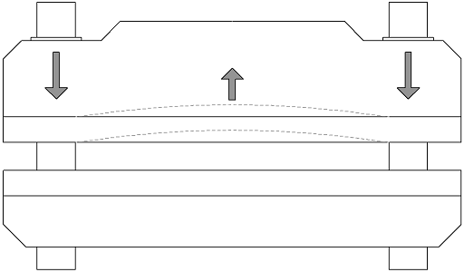
Proper brake maintenance, cleaning of dies and careful alignment are key first steps to ensuring accurate and reliable bending.  However even after taking the necessary precautions Bend Angles can still end up being irregular across the length of the bend due to crowning or other machine related flexing.  The most common form of flexing that occurs in a press brake is what is known as crowning.  Crowning occurs when the upper and lower beam, despite their often significant structure, flex away from the work piece in the center of the brake.  Most brakes are driven by two points at either ends of the press.  These points can be the cams of a mechanical brake or the cylinders of a hydraulic brake.  The entire force of the brake is driven through these two points, so the longer the beams, the more room for deflection.  Below shows a generic Brake Press whose upper beam is undergoing crowning. Before using shims to recover from the effects of crowning you should, if possible, bend your work piece at the center of the brake.  While this won’t eliminate the crowning it will center it on your tooling, making it easier to compensate for.
Brake Press Crowning When Bending Sheet Metal
Once the need for shimming has been established, and all other basic assurances have been made that the machine is functioning properly, you will begin to slowly add height to the areas where your Bend Angle is large.  The most effective method for shimming is removing the die and placing a piece of paper under the area where you are looking to shim.  Depending on your v opening a single sheet of paper can add as much as 1° to that area of the bend.  The larger the v opening the more shimming will be required to achieve this because the punch has to travel further in order to affect the work piece.  It is important to stress this level of precision to new operators in order to prevent dangerous over shimming on the first try.

Forming Shims

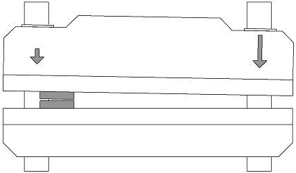
Another common situation which can be solved with shimming is the twisting of a Brake Press when the tooling is off center.  Many times a setup will call for different sections of a Brake Press to be used to bend different parts of a work piece.  This typically involves moving the work piece from one end to the other during the entire bending process.  When the work piece is at one end of the press it is going to unbalance the load at the other end.  This can at best force the machine to compensate with hydraulics, and at worst cause a machine stop or failure.  A Forming Shim is a piece of the same material which, already bent, can be placed inside the v opening at the far end of the brake, sometimes with the addition of a paper shim, in order to balance the load at the bottom of the bend.   This type of shim can run the entire length of the Brake Press is necessary in order to even out the load.  Forming shims are especially useful when Bottom Bending and Coining because the majority of the tonnage will be applied after the punch has made contact with the shim.
Form Shimming A Brake Press To Avoid Twisting
As you can see above, a bend operation set up on the left end of the brake causes uneven force to be applied, resulting in a twisting of the upper beam.  Even a single degree of rotation on the upper beam can be significant to the operation of the press.  In this operation adding a forming shim to the right end of this brake would have prevented the twisting from occurring.
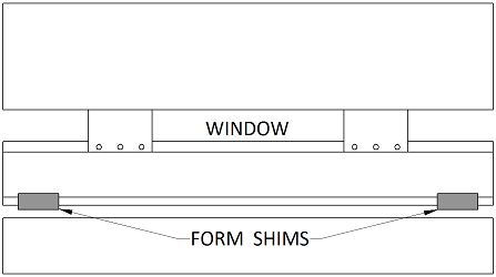
Forming Shims are also commonly seen on Window Punching operations because they help re-balance the load back into the center of the punch.  The shims are added to the punch area outside of the window.  This adds a layer of protection against crowning inside the window area.
Using A Form Shim To Compensate For Crowning On A Window Bend

Warning about Shimming

As we discussed proper maintenance, calibration and cleaning of your Brake Press will eliminate the majority of accuracy issues seen by operators in day to day operations.  Most modern brakes have methods of compensating for crowning and twisting which, while not always perfect, can be highly effective at reducing inaccuracies.  Coatings on materials, material tolerances, and stickers or labels added to parts can all cause bends to change along the bend lines.  While form shimming is rather benign, adding a shim underneath your die should be a last resort at correcting parts.  Over time the tooling will begin to wear in, adding an additional level of wear around the shim, resulting in the need for more shimming.  This can make the problem worse and eventually end up ruining the die.